Wiki
Contact
- Sho Nagao (Responsible person, DAQ, snagao@jlab.org, sho.nagao@nex.phys.s.u-tokyo.ac.jp)
- Alexandre Camsonne (JLab manager, camsonne@jlab.org)
- Ken Nishida (Detector, ken.nishida@nex.phys.s.u-tokyo.ac.jp)
- Ravindu Kumaragamage (Detector, ravindu@jlab.org)
Links
- Wiki (this page)
- Shift Table [https://docs.google.com/spreadsheets/d/1l6xSZyWtJp-qullufdNhQUQxzDeH2rkriUogHcKd2Kk/edit?usp=sharing]
- Beamtime Log Note [https://docs.google.com/document/d/1jugEdr5lsl8IZCmf_lVthm3e4gvbkZWo8eYAMRVqb88/edit?tab=t.0]
For shift personel
- Shift work is written at the top of the Shift Table. Each shift will take about 10 minutes. If you find anything strange, please contact an expert.
Troubleshooting
- Cannot find the latest pdf files.
- If the timestamp is within 30 minutes.
PDF files are generated & uploaded after the current run is over; since one run is 30 minutes, only PDFs up to at least 30 minutes previous run are uploaded. - No update for more than 1 hour
Raspberry pi or EASIROC or some other things may be down. Contact experts.
- If the timestamp is within 30 minutes.
For expert
This section describes DAQ operations during beamtime. For more information, check "How to operate new-firmware EASIROC and RaspberryPi".
How to handle remote power switch
Even if the EASIROC module or Raspberry Pi crash, you can reboot them via remote power swich. The procesure is as followed:
- Access to the VNC viewer on adaqsc computer
- Type
$ssh -L 5908:localhost:5908 -J knishida@hallgw.jlab.org aslow@adaqscon your local computer terminal - Open VNC client and type
vnc://localhost:5908. As for the required password, please ask to Ken, Kotaro, Sho and Alex. - Then, you can open
- Type
- Access to compton computer from asdaq terminal
- Type
$ssh compton@compton(ask password to Ken, Kotaro, Sho and Alex)
- Type
- Start firefox web browser on compton computer
- Type just
firefoxon the terminal, the firefox browser will pop up. - Type
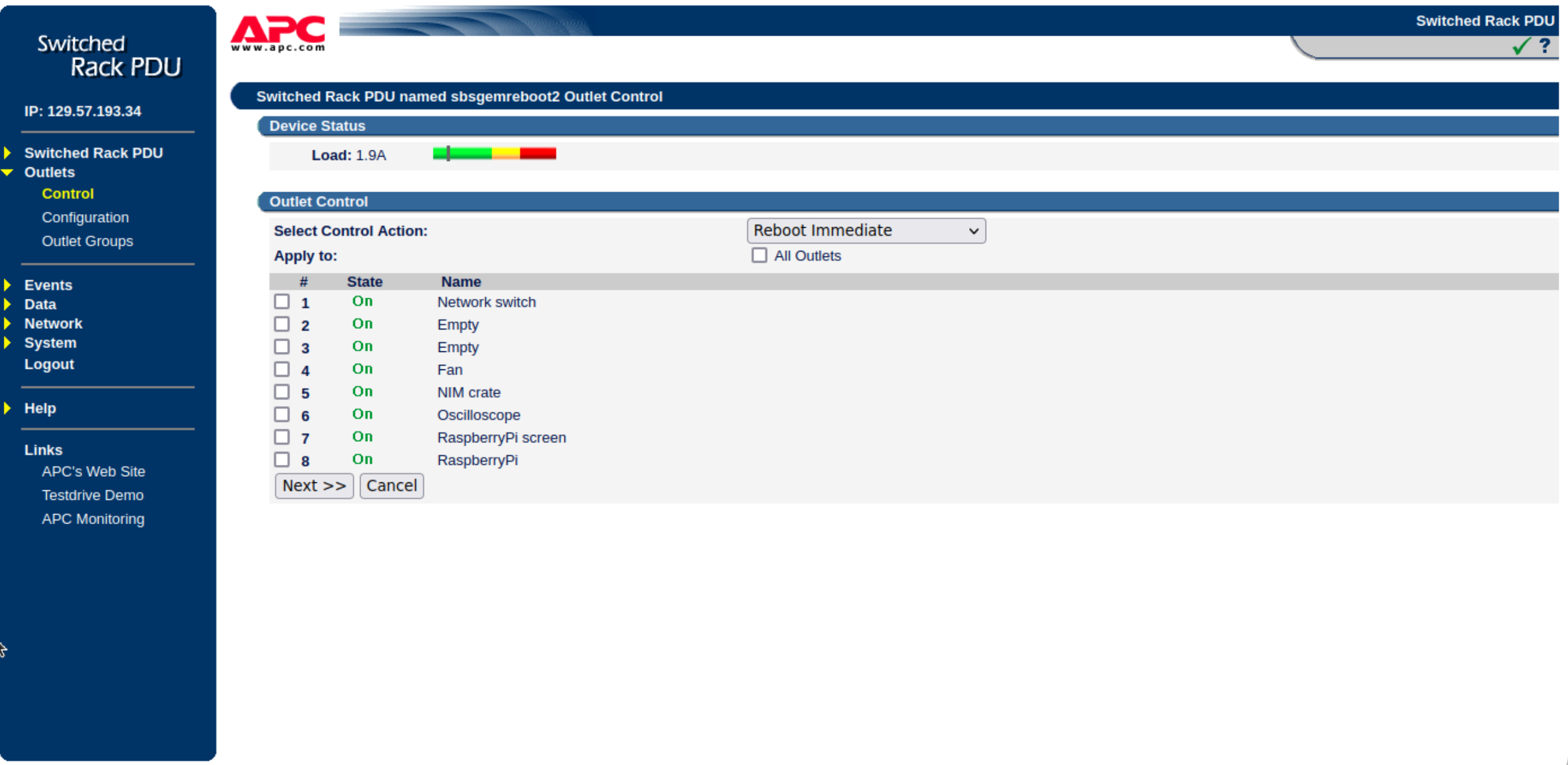
129.57.193.34on the browser and enter "username" and "password" (Ask them to Ken, Kotaro, Sho and Alex), then you will get a window shown below:
- Type just
- Reboot on browser controller
- Select
#5 NIM Crateto reboot EASIROC or select#8 Raspberry Pito reboot Raspberry Pi. - Select "Reboot immediate" and push "next>>" and "apply".
Then, you can reboot them. Retry to check the connection to Raspberry Pi or EASIROC.
- Select
After reboot raspberry pi
If you have restarted raspberry pi due to some trouble, please follow the procedure below to restore it.- Login and move to "/home/nex/NIM_EASIROC/controller" dir.
- Open a new tmux session "Controller"
$ tmux new -s Controller./Controller.rb
- Check HV status
statusHV
- Set HV if needed
increaseHV 56.0
- Detach session
ctrl+b, d
- Move to analysis dir.
- Open a new tmux session "MergeLog" and run MergeLog.py
python MergeLog.pyctrl+b, d
- Open a new tmux session "PlotLog"
./plotlog.shctrl+b, d- If this shell script outputs errors, it may contain unexpected text in the log file. Delete the line from run_xxxx.log and try it again.
Checking EASIROC Controller
NOTE: Never open multiple Controller.rb. Before open it, check running jobs with "ps x" command.Procedure
- Login to the RaspberryPi.
ssh -Y nex@129.57.193.11
- Open tmux window.
tmux a -t Controller
- Execute ruby script. The current directory should be "/home/nex/NIM_EASIROC/controller".
./Controller.rb
- Increase HV. NOTE:"Tab" doesn't work on Controller.rb.
increaseHV 56.0
- Check HV. Typical V / A = 55.97V / 7.2 uA.
statusHV
- Set DAQ mode.
adc ontdc onscaler on
- Start DAQ. If you want to stop, type
stopduring data taking. This "stop" command does not work while "Reading monitor ADC" or "Switching now" is in progress. Please enter it when the progress bar is moving.readloop
- Exit the script if you want.
exit
- If you want to close tmux terminal, type
- Ctrl+b, d
- Check tmux list
tmux ls - Open new session
tmux new -s session_name - Open running session
tmux a -t session_name - Detach tmux session
Ctrl+b, d - Close tmux session
exit
Data (.dat), compressed data (.tar.xz), log (.log), and run settings (runlist.csv) are automatically generated in the data directory. The shift person simply checks to see if the data collection is working. If it is working as usual, "readloop" will automatically collect the data without doing anything.
If you find anything strange, please contact Alex, Sho and Ken.
List of equipement from Japan
- SiPM 3ch Box Qty.4
- Special 30m LAN cable Qty.4
- Raspberry Pi5 Qty.1
- 7 inch Monitor Qty.1
- USB-LAN connector Qty.1
- Standard LAN cable Qty.2
- NIM EASIROC Qty.1
- TTL-NIM-TTL 8ch module Qty.1 (https://www.kagaku.com/hoshin/n002.html, 1ch TTLtoNIM, 4ch NIM-TTL will be used)
- 2ch Gate&Delay Module Qty.2 (http://www.tcnland.co.jp/archives/product_type/gatedelaygenerator_n-tm_307, 4ch G&D will be used)
- 4ch logic fan I/O Qty.1 (http://www.tcnland.co.jp/archives/product_type/fanin%EF%BC%8Ffanout_n-tm_102, 2ch will be used)
The SiPM is 3ch SiPM Box x 4 = 12 ch total. All SiPM can be handled by the adobe items.
For 8.~10., please arrange for spare modules in case the modules sent from Japan are defective. Equivalent products are fine.
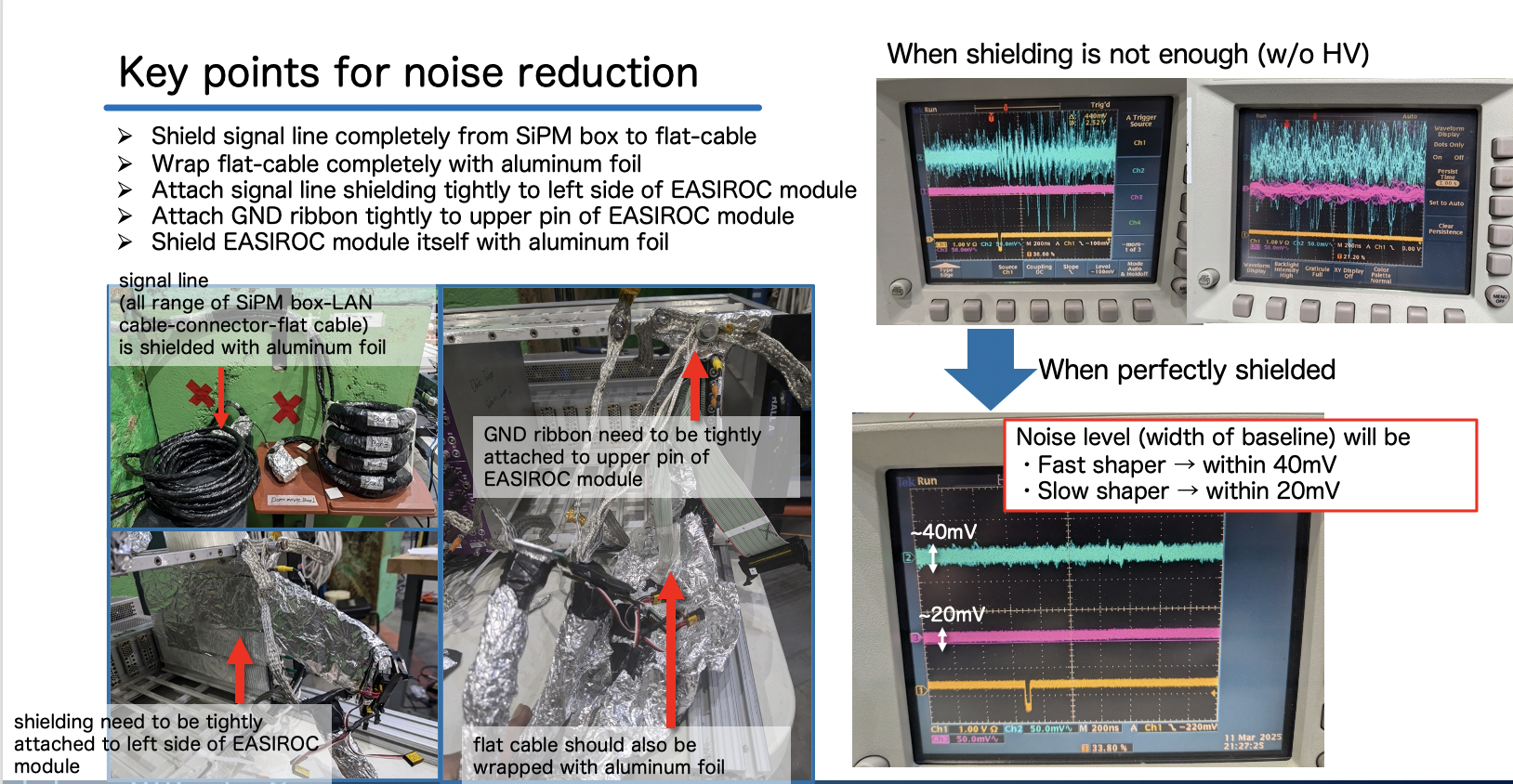
We were unable to handle the detector well due to the effects of noise and crosstalk from TTL with standard cat.7 LAN cables or ECL Flat cables. We will provide a cable with an additional shield on the cat.7 cable.
Old map of Hall A for previous SBS experiment
- https://userweb.jlab.org/~efuchey/SBS_BB/Pictures/GlobalPlanHallAFloor_lowBBangle.pdf
- https://redmine.jlab.org/documents/118
How to operate new-firmware EASIROC and RaspberryPi
- Access to RaspberryPi
- IP address : 129.57.193.11
- Password : Please ask Ken
- Can access via JLab hall-gateway
- RasbberryPi controls EASIROC, edits EASIROC parameter files, saves aquired data by EASIROC, and outputs TTL signal for LED.
- Turn on LED in SiPM Boxes
- Each SiPM box has LED so that we can see 1p.e. level signal clearly.
- LEDs flash by sending TTL signal from RaspberryPi via BNC cable at 200Hz. This TTL signal is also used for DAQ trigger.
- Execute
python gpio_led.pyto start sending TTL and turning on LED. While executinggpio_led.py, you can see TTL signal on oscilloscope ch1. - Execute
python gpio_pedestal.pyto take ADC pedestal data. While executinggpio_pedestal.py, you cannot see TTL signal on oscilloscope. - LED emission intensity is very sensitive to width and amplitude of TTL signal. Ken has already adjusted it, so please don't touch NIM gate& delay generator and variable register.
- You can edit
GPIO.pyscript and selectPedestal mode/LED mode. InPedestal mode, you will aquire only pedestal data (without 1p.e. signal), while inLED mode, you will aquire 1p.e. data.
- Boot EASIROC
- Confirm power supply to NIM crate, RaspberryPi is OK
- Once power is supplied to EASIROC correctly, LED1 at the bottom of EASIROC module turns red
- Main directory of EASIROC operation files on RaspberryPi
cd ~/EASIROC: main directory
Controller.rb: EASIROC controller script
GPIO.py: TTL signal for LED
yaml: EASIROC parameter files.RegisterValue.yamlis the only parameter file we need to edit.
data: Data files (both .dat & .root). Once DAQ is completed, both rawdata(.dat) and decoded root file(.root) are output automatically in this directory. - Boot EASIROC (IP:
192.168.10.21)
./Controller.rb [IP address]
- Command to operate EASIROC
./Controller.rb [IP address]will open interactive EASIROC controller.helpcommand will show available interactive commands- Basic commands we will use are:
 setHV [bias voltage] : Set SiPM HV as [bias voltage] value.
 statusHV : Show HV & current value on SiPMs.
 slowcontrol : Reflect changes on slow-controller setting (every time after you edit RegisterValue.yaml ).
 tdc on/off : TDC data taking ON/OFF. You can basically set as "ON".
 adc on/off : ADC data taking ON/OFF. You can basically set as "ON".
 scaler on/off : Scaler data taking ON/OFF. You can basically set as "ON".
 read [EventNumber] [Filename] : Start data taking. Data taking will go at 200Hz and EventNum around 10000-50000 looks fine. Filename is currently like "test000x.dat".
- Caution0: EASIROC is ASIC module and is very weak for example against over-current caused by your wrong HV operation. Please be careful when you operate EASIROC not to break it, and please ask Ken if you have something unclear before doing it.
- Caution1: When setting SiPM HV, you should increase SIPM HV gradually like 0V->20V->40V->50V->53V->54.5V. You can see 1p.e. signals from SiPM at 53V. If you cannot see the signals at 53V, you have some mistakes or troubles like HV line is not connected correctly. Also, be careful not to set SiPM HV larger than 56V. Please check your input value every time you use
setHVcommand. HV will be enough at around 54.5V or 55.0V. Please check HV & current status frequently withstatusHVcommand.
- Caution2: Every time before disconnecting HV line or shutting down EASIROC, you should decrease SiPM HV gradually with
setHVcommand. Don't cut off HV suddenly.
- Caution3: Sometimes, EASIROC interactive mode may unexpectedly and suddenly closed while you are operating it. Basically, EASIROC is designed to decrease HV gradually in even such cases not to damage SiPM and EASIROC itself. So, you don't worry about it too much, but please let Ken know if some troubles happen.
- Edit EASIROC parameter file
- By editing
RegisterValue.yaml, you can change some shaping parameter in EASIROC. However, only you need to change may be EASIROC channel you want to monitor signal with oscilloscope. RegisterValue.yamlis like as below:EASIROC1: Capacitor HG PA Fdbck: 200fF Capacitor LG PA Fdbck: 200fF Time Constant HG Shaper: 150ns Time Constant LG Shaper: 100ns DAC code: 700 EASIROC2: Capacitor HG PA Fdbck: same Capacitor LG PA Fdbck: same Time Constant HG Shaper: same Time Constant LG Shaper: same DAC code: same High Gain Channel 1: 4 High Gain Channel 2: -1 Probe Channel 1: 4 Probe Channel 2: -1 Probe 1: Out_fs Probe 2: Out_fs #Out_PA_HG,Out_PA_LG,Out_ssh_HG,Out_ssh_LG,Out_fs SelectableLogic: Pattern: Or64 #OneCh_#,Or32u,Or32d,Or64,Or32And,Or16And,And32u,And32d,And64,And32Or HitNum Threshold: 4 # Threshold for each OR logic. 0~64. Default: 0 And Channels: -1 # Cannels used in And Logic. 0~63. Default: -1 TimeWindow: 4095ns UsrClkOut: "OFF" #"OFF","ON",1Hz,10Hz,100Hz,1kHz.10kHz,100kHz,3MHz,25MHz Trigger: ## This "Trigger" values are not used for this version. Mode: 0 #0-7 DelayTrigger: -1 #500MHz #default:-1, 0-253 #trig -> hold -> l1 -> l2 DelayHold: -1 #25MHz DelayL1Trig: -1 #6MHz Width: raw
In this script,HG Channle 1 : [channel number]is output channel of HG Out 1 from the front panel of EASIROC module. HG Out 1 is set so that you can monitor Slow-sheper analog output from each channel.Probe 1 : [channel number]is output channel of Probe 1 from the front panel of EASIROC module. Probe 1 is set so that you can monitor Fast-sheper analog output from each channel.
- For example, when checking signal of Box2, you can edit
RegisterValue.yamlasHG Channle 1 : 4andProbe 1 : 4to monitor fast/slow shaper analog signal from channel 4 (=MPPC4) with oscilloscope. Don't forgetslowcontrolcommand to reflect the change.
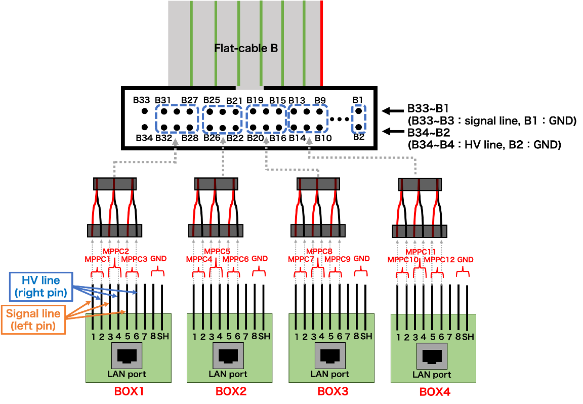
Signal line & HV line connection
- Connection around EASIROC module
- We have 4 SiPM boxes and

- Channel assign of MPPC/EASIROC
BOX BOX1 BOX2 BOX3 BOX4 TTL (BNC cable) TTL1 TTL2 TTL3 TTL4 Signal&HV line(LAN cable) LAN1 LAN2 LAN3 LAN4 MPPC 1 2 3 4 5 6 7 8 9 10 11 12 EASIROC ch 1 2 3 4 5 6 7 8 9 10 11 12
Check signals with oscilloscope
- How SiPM signals are processed inside EASIROC
- EASIROC is ASIC-based stand-alone DAQ module. It can amp.&shaping SiPM raw analog signal, and it extracts TDC, ADC, Scaler data inside itself(stand-alone). Already processed 64-bit(?) data is sent from EASIROC to RaspberryPi.

- 4ch oscilloscope is assigned as followed:
ch1: (50ohm impedance, 1V/div.) TTL signal from RaspberryPi -> use oscilloscope trigger
ch2: (1Mohm impedance, 50mV/div.) Fast-shaper analog output from EASIROC
ch3: (1Mohm impedance, 50mV/div.) Slow-shaper analog output from EASIROC
ch4: (50ohm impedance, 1V/div.) Hold timing signal
As for orizontal scale, around 200ns/div will be good.
How to remove noise on SiPM signal
Updated by Ken Nishida 10 months ago · 21 revisions